|
|
In a previous tutorial we showed how to install Openvswitch on Qemu image with Microcore Linux. At the end of tutorial we created Openvswitch extension and submitted it to Microcore upstream. Assuming that Openvswitch is configured and functional, we are ready to make three labs which helps us to test features such as VLANs, trunks and interVLAN routing.
LAB 1 Access VLAN Configuration And Testing
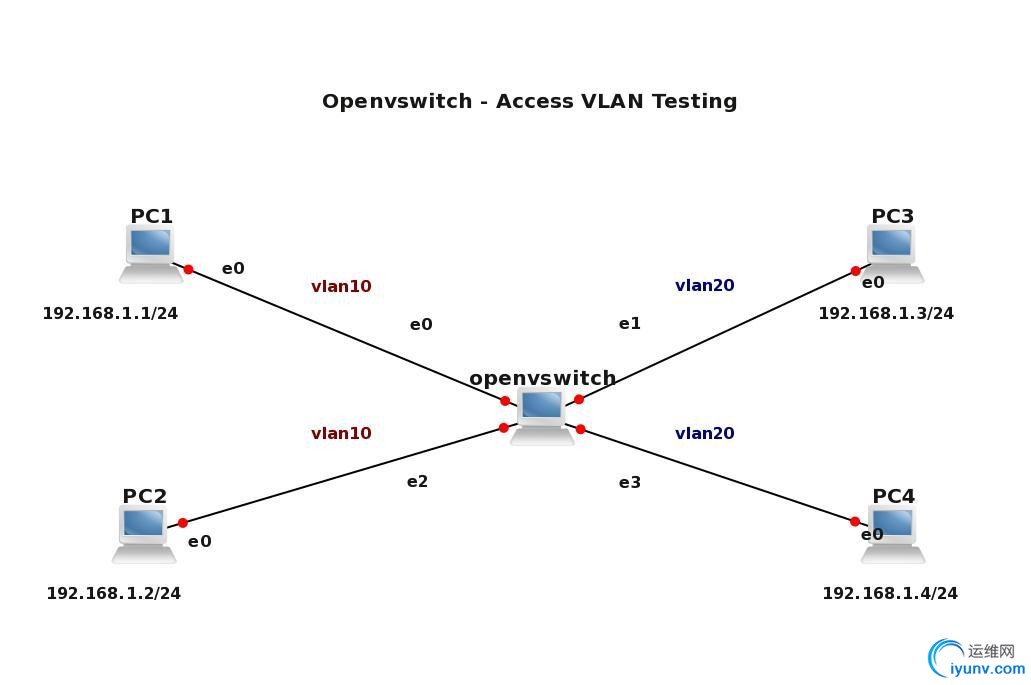
In this lab we are going to test connectivity between PCs which reside in same VLAN. PC1 and PC2 are assigned to VLAN 10 and PC3 and PC4 reside in VLAN 20. According to theory, each VLAN should have its own separate subnet. In our case, we are going to test not only connectivity between computers in the same VLANs but also to test connectivity between PCs placed in different VLAN.
For this reason I chose one subnet 192.168.1.0/24 for all the computers so L3 connectivity exists between e.g. PC1 (VLAN 10) and PC3 (VLAN20). Of course, the computers assigned to different VLANs are separated on Layer 2 so we do not expect any connectivity between those computers.

Figure 1 Openvswitch with configured VLANs on its access ports – click image to enlarge
1) Openvswitch configuration
Login is tc without password set.
a) Let’s create bridge br0
sudo ovs-vsctl add-br br0
b) Add access port eth0 to the bridge br0 and assign it to VLAN 10
sudo ovs-vsctl add-port br0 br0 eth0 tag=10
c) Assign remaining ports to the br0
sudo ovs-vsctl add-port br0 eth2 tag=10
sudo ovs-vsctl add-port br0 eth1 tag=20
sudo ovs-vsctl add-port br0 eth3 tag=20
d) Assign hostname to Microcore
sudo hostname openvswitch
echo "hostname openvswitch" >> /opt/bootlocal.sh
e) Save conf.db file to keep it persistent after the next reboot of Microcore Linux
/usr/bin/filetool.sh -b
2) PC1 configuration
Login is tc without password set.
Assign IP address 192.168.1.1/24 to eth0 and make it persistent after next reboot of Microcore
sudo hostname PC1
sudo ifconfig eth0 192.168.1.1 netmask 255.255.255.0
echo "hostname PC1" >> /opt/bootlocal.sh
echo "ifconfig eth0 192.168.1.1 netmask 255.255.255.0" >> /opt/bootlocal.sh
/usr/bin/filetool.sh -b
3) PC2 to PC4 configuration
Configure all remaining computers with correct IP paramters, similary as it was done in point 2)..
4) Access VLAN connectivity test
a) Connectivity test between PC which are residing in the same VLAN
Issue ping from PC1 (VLAN10) to PC2 (VLAN10).
tc@bPC1:~$ ping 192.168.1.2
PING 192.168.1.2 (192.168.1.2): 56 data bytes
64 bytes from 192.168.1.2: seq=0 ttl=64 time=26.666 ms
64 bytes from 192.168.1.2: seq=1 ttl=64 time=0.000 ms
64 bytes from 192.168.1.2: seq=2 ttl=64 time=3.334 ms
64 bytes from 192.168.1.2: seq=3 ttl=64 time=0.000 ms
— 192.168.1.2 ping statistics —
4 packets transmitted, 4 packets received, 0% packet loss
round-trip min/avg/max = 0.000/6.000/26.666 ms
tc@PC1:~$
Issue ping from PC3 (VLAN20) to PC4 (VLAN20).
tc@PC3:~$ ping 192.168.1.4
PING 192.168.1.4 (192.168.1.4): 56 data bytes
64 bytes from 192.168.1.4: seq=0 ttl=64 time=3.334 ms
64 bytes from 192.168.1.4: seq=1 ttl=64 time=3.333 ms
64 bytes from 192.168.1.4: seq=2 ttl=64 time=3.333 ms
64 bytes from 192.168.1.4: seq=3 ttl=64 time=0.000 ms
— 192.168.1.4 ping statistics —
4 packets transmitted, 4 packets received, 0% packet loss
round-trip min/avg/max = 0.000/1.666/3.334 ms
tc@PC3:~$
As we have expected ping should have worked in both cases.
b) Test connectivity between computers placed to different VLANs
Issue ping from PC1 (VLAN10) to PC3 (VLAN20).
tc@PC1:~$ ping 192.168.1.4
PING 192.168.1.4 (192.168.1.4): 56 data bytes
— 192.168.1.4 ping statistics —
11 packets transmitted, 0 packets received, 100% packet loss
We can see that ping is not working between PC1 and PC3. We confirm that there is not connectivity between computers placed in to different VLANs and openvswitch is working correctly.
LAB 2 VLAN Trunk Configuration And Testing
In previous LAB we proved, that openvswitch only forwards traffic between computers which reside in the same VLAN. In this LAB we are going to add additional switch to the topology – openvswitch2 and connect switches with link configured as 8021.1q trunk. The access VLAN 10, 20, 30 is added to openvswitch2 and VLAN 30 is added to openvswitch. There is only VLAN 10 and 30 allowed on both sides of the trunk.
Our goal is to show that only traffic from VLAN 10 and VLAN 30 is forwarded between switches.

Figure 2 Two openvswitches connected with a link configured as 8021.q trunk – click image to enlarge
1) Openvswitch configuration
Assuming that the previous configuration of openvswitch has been stored, we only add following commands.
a) Add access port eth4 to the bridge br0 and assign it to VLAN 30
sudo ovs-vsctl add-port br0 eth4 tag=30
b) Add trunk port eth5 to bridge br0 and allow VLAN 10 and 30 on the trunk
sudo ovs-vsctl add-port br0 eth5 trunks=10,30
c) Save configuration of Microcore
/usr/bin/filetool.sh -b
2) Openvswitch2 configuration
As it was explained every single step of configuration of openvswitch in previous examples I am going to skip it now.
sudo hostname openvswitch2
echo "hostname openvswitch2" >> /opt/bootlocal.sh
sudo ovs-vsctl add-br br0
sudo ovs-vsctl add-port br0 eth5 trunks=10,30
sudo ovs-vsctl add-port br0 eth0 tag=30
sudo ovs-vsctl add-port br0 eth1 tag=20
sudo ovs-vsctl add-port br0 eth2 tag=10
/usr/bin/filetool.sh -b
Similarity, configure IP parameters for the PC5, PC6 to PC8 according to the topology.
3) Trunk VLAN test
a) Issue the ping from PC1 (VLAN10) to PC8 (VLAN10)
tc@PC1:~$ ping 192.168.1.8
PING 192.168.1.8 (192.168.1.8): 56 data bytes
64 bytes from 192.168.1.8: seq=0 ttl=64 time=6.667 ms
64 bytes from 192.168.1.8: seq=1 ttl=64 time=3.333 ms
64 bytes from 192.168.1.8: seq=2 ttl=64 time=0.000 ms
64 bytes from 192.168.1.8: seq=3 ttl=64 time=3.334 ms
^C
— 192.168.1.8 ping statistics —
4 packets transmitted, 4 packets received, 0% packet loss
round-trip min/avg/max = 0.000/3.333/6.667 ms
tc@PC1:~$
We can see that traffic in VLAN 10 is succesfully transferred through trunk. If the same VLAN exists on two switches we call it end-to-end VLAN.
b) Issue the ping from PC5 (VLAN30) to PC6 (VLAN30)
tc@PC5:~$ ping 192.168.1.6
PING 192.168.1.6 (192.168.1.6): 56 data bytes
64 bytes from 192.168.1.6: seq=0 ttl=64 time=6.667 ms
64 bytes from 192.168.1.6: seq=1 ttl=64 time=3.334 ms
64 bytes from 192.168.1.6: seq=2 ttl=64 time=3.333 ms
64 bytes from 192.168.1.6: seq=3 ttl=64 time=3.333 ms
^C
— 192.168.1.6 ping statistics —
4 packets transmitted, 4 packets received, 0% packet loss
round-trip min/avg/max = 3.333/4.166/6.667 ms
tc@PC5:~$
From what we see, trunk is successfully carrying the traffic marked with tag 30 between switches.
c) Issue the ping from PC3 (VLAN20) to PC7 (VLAN20)
tc@PC3:~$ ping 192.168.1.7
PING 192.168.1.7 (192.168.1.7): 56 data bytes
— 192.168.1.7 ping statistics —
6 packets transmitted, 0 packets received, 100% packet loss
tc@PC3:~$
Traffic from vlan 20 is not forwarded between switches. It is because VLAN 20 is not allowed on the trunk. If there would be need to allow all the VLANs on the trunk, only parameter trunks (without specific VLAN) should be presented.
LAB 3 L3 VLAN interfaces, InterVLAN routing – Configuration And Testing
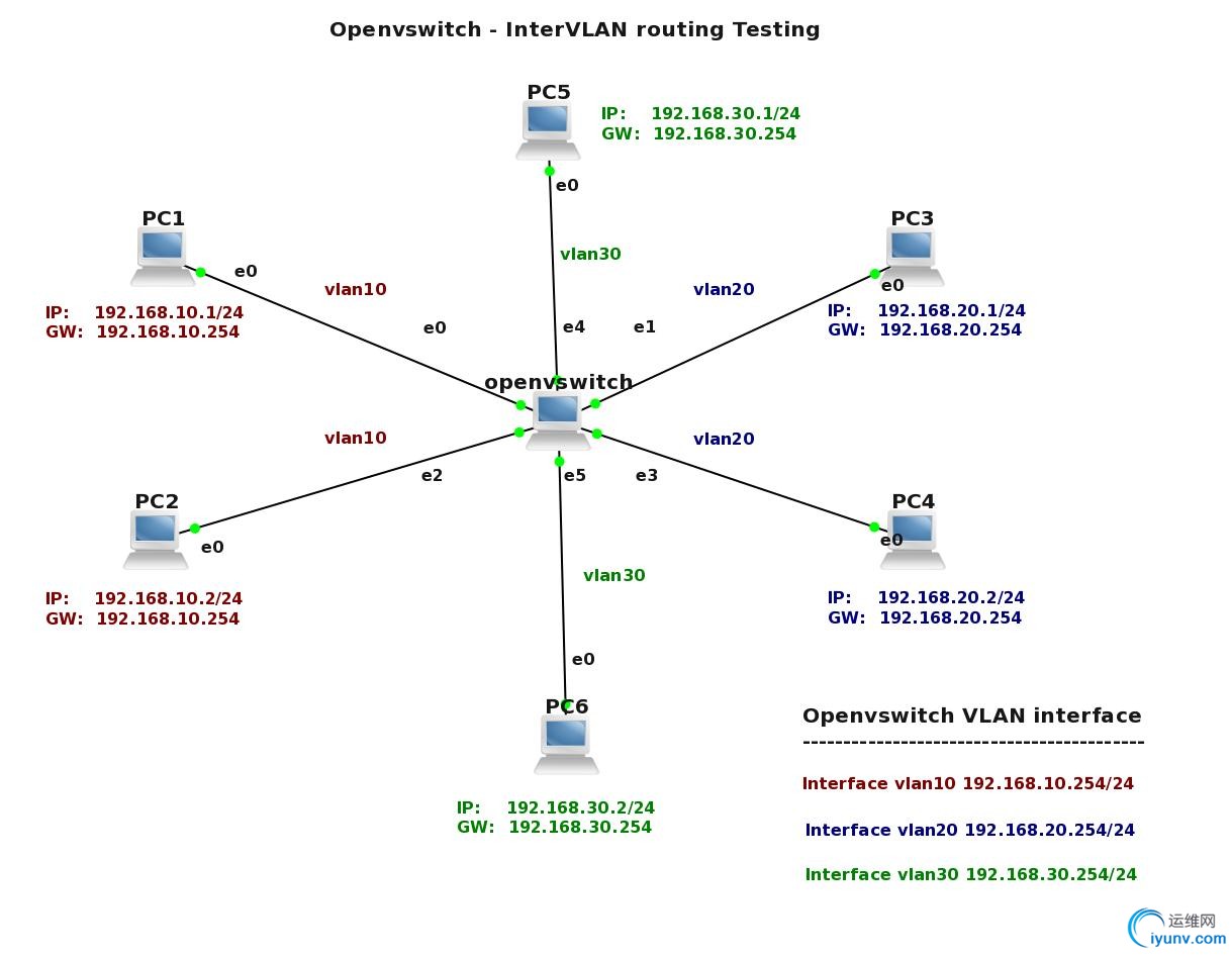
In this last LAB we are going to create L3 VLAN interface for VLAN 10, 20, 30. After that we will check if Microcore can forward traffic between different VLANs. We assume that particular ports were added to VLANs in previous LABs and only additional configuration will be shown in this LAB. I have also changed a topology to make it more simple and create the new IP plan for the devices.

Figure 3 Topology for InterVLAN routing testing – click image to enlarge
1) Openvswitch configuration
a) Add an internal port vlan10 to bridge br0 as a VLAN access port for VLAN 10
sudo ovs-vsctl add-port br0 vlan10 tag=10 -- set interface vlan10 type=internal
b) Create vlan20 and vlan30 interfaces
sudo ovs-vsctl add-port br0 vlan20 tag=20 -- set interface vlan20 type=internal
sudo ovs-vsctl add-port br0 vlan30 tag=30 -- set interface vlan30 type=internal
c) Add access port eth4 and eth5 to the bridge br0 and assigned them to VLAN 30
First, We need to delete configuration for eth4 and eth5 that was done for LAB1
and LAB2.
sudo ovs-vsctl del-port br0 eth4
sudo ovs-vsctl del-port br0 eth5
Now we can assign ports to the VLAN 30.
sudo ovs-vsctl add-port br0 eth4 tag=30
sudo ovs-vsctl add-port br0 eth5 tag=30
d) Assign IP adresses to the VLAN interfaces
sudo ifconfig vlan10 192.168.10.254 netmask 255.255.255.0
sudo ifconfig vlan20 192.168.20.254 netmask 255.255.255.0
sudo ifconfig vlan30 192.168.30.254 netmask 255.255.255.0
echo "ifconfig vlan10 192.168.10.254 netmask 255.255.255.0" >> /opt/bootlocal.sh
echo "ifconfig vlan20 192.168.20.254 netmask 255.255.255.0" >> /opt/bootlocal.sh
echo "ifconfig vlan30 192.168.30.254 netmask 255.255.255.0" >> /opt/bootlocal.sh
/usr/bin/filetool.sh -b
e) Enable IPv4 and IPV6 packets forwarding between interfaces
Forwarding between network interfaces is disabled by default. To activate ipv4
and ipv6 forwarding for Microcore you need to enable it:
sudo sysctl -w net.ipv4.ip_forward=1
sudo sysctl -w net.ipv6.conf.all.forwarding=1
echo "sysctl -w net.ipv4.ip_forward=1" >> /opt/bootlocal.sh
echo "sysctl -w net.ipv6.conf.all.forwarding=1" >> /opt/bootlocal.sh
/usr/bin/filetool.sh -b
2) PC1 to PC6 – IP address, netmask, default gateway – configuration
a) Delete old IP addresses from the computers
We should split IP address space in such way when each VLAN would have assigned separate subnet. First, for each computer delete a row with old IP address from /opt/bootlocal.sh which was previously assigned in LAB1 (use dd command for delete of particular row).
b) Assign IP address and default GW to PC1 to PC6
Example for PC1:
sudo ifconfig eth0 192.168.10.1 netmask 255.255.255.0
sudo route add default gw 192.168.10.254
echo "ifconfig eth0 192.168.10.1 netmask 255.255.255.0" >> /opt/bootlocal.sh
echo "route add default gw 192.168.10.254" >> /opt/bootlocal.sh
/usr/bin/filetool.sh -b
Similiary, do it for all the PCs, according to topology and IP address plan.
3) InterVLAN routing testing
As long as PCs have had correct IP address, netmask and default gateway assigned, we can either ping PC in the same VLAN or any other vlan interface.
a) Issue ping from PC1 (VLAN10) to PC2 (VLAN10)
tc@PC1:~$ ping 192.168.10.2
PING 192.168.10.2 (192.168.10.2): 56 data bytes
64 bytes from 192.168.10.2: seq=0 ttl=64 time=3.333 ms
64 bytes from 192.168.10.2: seq=1 ttl=64 time=3.333 ms
64 bytes from 192.168.10.2: seq=2 ttl=64 time=3.334 ms
64 bytes from 192.168.10.2: seq=3 ttl=64 time=3.333 ms
— 192.168.10.2 ping statistics —
4 packets transmitted, 4 packets received, 0% packet loss
round-trip min/avg/max = 3.333/3.333/3.334 ms
tc@PC1:~$
b) Issue ping from PC1 (VLAN10) to interface vlan20
tc@PC1:~$ ping 192.168.20.254
PING 192.168.20.254 (192.168.20.254): 56 data bytes
64 bytes from 192.168.20.254: seq=0 ttl=64 time=3.333 ms
64 bytes from 192.168.20.254: seq=1 ttl=64 time=0.000 ms
64 bytes from 192.168.20.254: seq=2 ttl=64 time=0.000 ms
64 bytes from 192.168.20.254: seq=3 ttl=64 time=3.333 ms
— 192.168.20.254 ping statistics —
4 packets transmitted, 4 packets received, 0% packet loss
round-trip min/avg/max = 0.000/1.666/3.333 ms
tc@PC1:~$
We can see that in both cases, ping was succesfull.
c) Issue the ping from PC1 (VLAN10) to PC3 (VLAN20)
tc@PC1:~$ ping 192.168.20.1
PING 192.168.20.1 (192.168.20.1): 56 data bytes
64 bytes from 192.168.20.1: seq=0 ttl=63 time=0.000 ms
64 bytes from 192.168.20.1: seq=1 ttl=63 time=3.333 ms
64 bytes from 192.168.20.1: seq=2 ttl=63 time=3.333 ms
64 bytes from 192.168.20.1: seq=3 ttl=63 time=3.334 ms
— 192.168.20.1 ping statistics —
4 packets transmitted, 4 packets received, 0% packet loss
round-trip min/avg/max = 0.000/2.500/3.334 ms
tc@PC1:~$
Thanks to enabled forwarding between interfaces in kernel, ping is working between different VLANS. Microcore with Openvswitch is acting as the Layer3 switch.
End. |
|